Door Sensor w/ Reed Switch & Piezo
← Back to Projects1.0 Introduction
1.1 Background
In Spring 2025, our final project for Engineering 11 was to design and prototype a practical engineering product. After brainstorming and evaluating multiple ideas, we decided to create a door sensor. The purpose of this device is to detect the opening of a door using a magnetic switch and to alert the user with a sound via a mini piezo buzzer. This simple, compact, and effective system enhances home security and accessibility, especially for individuals needing sound-based alerts.
2.0 Design Problem Formulation
2.1 Filling a Niche
While many commercial door sensors exist, many are expensive, bulky, or require Wi-Fi and smartphone integration. Our goal was to build a low-cost, battery-powered, stand-alone door sensor with audible feedback, suitable for dorms, homes, or tool sheds.
2.2 Market Surveying
We explored multiple concepts before settling on our final design. Below are our initial and alternative ideas:
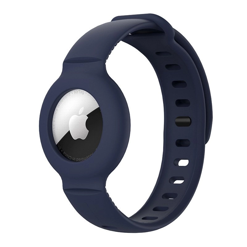
1. Tracking Bracelet:
A sensor placed near the entrance detects if the wearer crosses the threshold and triggers an alarm, alerting caretakers. This idea was appealing but limited in scenarios with many people in a room.
Price Estimate: $50

2. Ring-style Camera Monitoring:
A camera near the door monitors activity and sends alerts to a smartphone. Provides strong monitoring but is costly and requires internet connectivity.
Price Estimate: $80

3. RFID-based System:
RFID tags and a reader at the door detect passage of tracked individuals or objects. Effective but more expensive and requires tag management.
Price Estimate: $60–$100
2.3 Performance Requirements
- Cost under $200
- Fit within 1.5 × 1 × 1 cm housing
- Sound a piezo buzzer when the door opens
- Run on a small battery ~3–6 months
- Indoor use (32°F–104°F / 0°C–40°C); keep dry; avoid direct sun/moisture
2.4 Customer Satisfaction Curves
To evaluate user satisfaction, we developed a set of curves illustrating how customer satisfaction varies with different performance factors. These include runtime (before battery change), price, and power consumption. Our goal was to ensure that our design choices align with the expectations and preferences of potential users.

Runtime Satisfaction — increases steadily with longer runtime before battery change.

Price Satisfaction — decreases as cost increases.
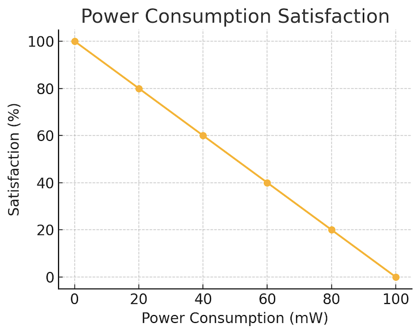
Power Consumption Satisfaction — lower consumption leads to higher satisfaction.
3.0 Project Engineering
3.1 Work Scope
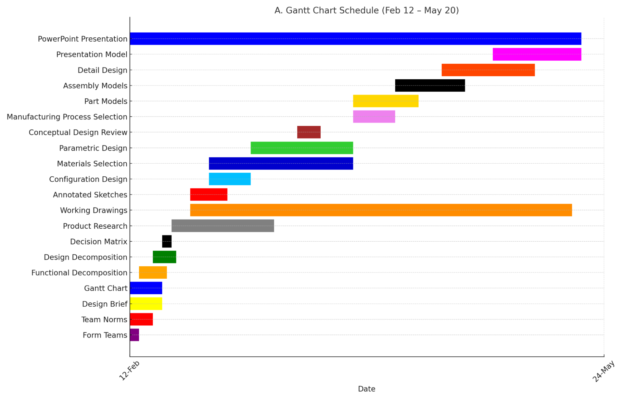
The development of the door sensor project was completed over the course of six weeks. The scope of work included idea generation, component research, prototyping, testing, and documentation. A Gantt chart was used to plan and track progress throughout the phases of the project (see Appendix A). Team meetings were held weekly to share updates, troubleshoot issues, and assign tasks. Communication was maintained through group messaging and shared documents on Discord and Drive.
Final deliverables included:
- A working prototype of the door sensor
- CAD sketches of the housing
- A performance test report
- A finalized bill of materials (BOM)
- Full project documentation, including this report
3.2 Team Roles and Responsibilities
Each team member contributed to the design and execution of the project. While roles overlapped in certain areas, the responsibilities were distributed as follows:
Ryan Huynh
- Circuit design and breadboarding
- Report writing and editing
- 3D housing design and CAD modeling
Adrian Vinuya
- Final assembly and testing
- Soldering and reed switch integration
- Bill of materials organization
Arielah Arana
- Prototyping and debugging
- 3D printing and enclosure assembly
- Maintenance planning and cost estimation
The team collaborated closely to ensure all deadlines were met, with flexibility built into the schedule to allow for iterative improvements and troubleshooting.
4.0 Conceptual Design
In the conceptual design phase, our team explored and evaluated multiple possible solutions before selecting the final approach. Each concept offered distinct advantages and trade-offs, which were compared using a weighted rating matrix.
4.1 Design Concept Alternatives
Concept 1 — Wearable Safe-Space Alarm
A system using trackers worn by individuals. If a tracked person exits through the door, the receiver triggers an alarm to alert caregivers.
- Pros: Provides monitoring for vulnerable users (e.g., elderly or children).
- Cons: Requires every user to wear a device; higher cost and complexity.
Concept 2 — Ring-style Camera Monitoring
A camera mounted near the entrance detects movement and sends notifications to a smartphone app.
- Pros: Remote monitoring, integrates with smart devices.
- Cons: Expensive, requires Wi-Fi and app setup, higher maintenance.
Concept 3 — Final Design (Chosen)✅
A simple reed switch paired with a piezo buzzer and coin-cell battery. When the door opens, the magnet separates from the reed switch, closing the circuit and activating the buzzer.
- Pros: Low cost, simple construction, reliable, energy efficient.
- Cons: Provides only local alerts, requires proper magnet alignment.
4.2 Weighted Rating Matrix
The concepts were evaluated against key criteria such as cost, reliability, simplicity, and power consumption. The reed-switch design achieved the highest score, making it the preferred solution.
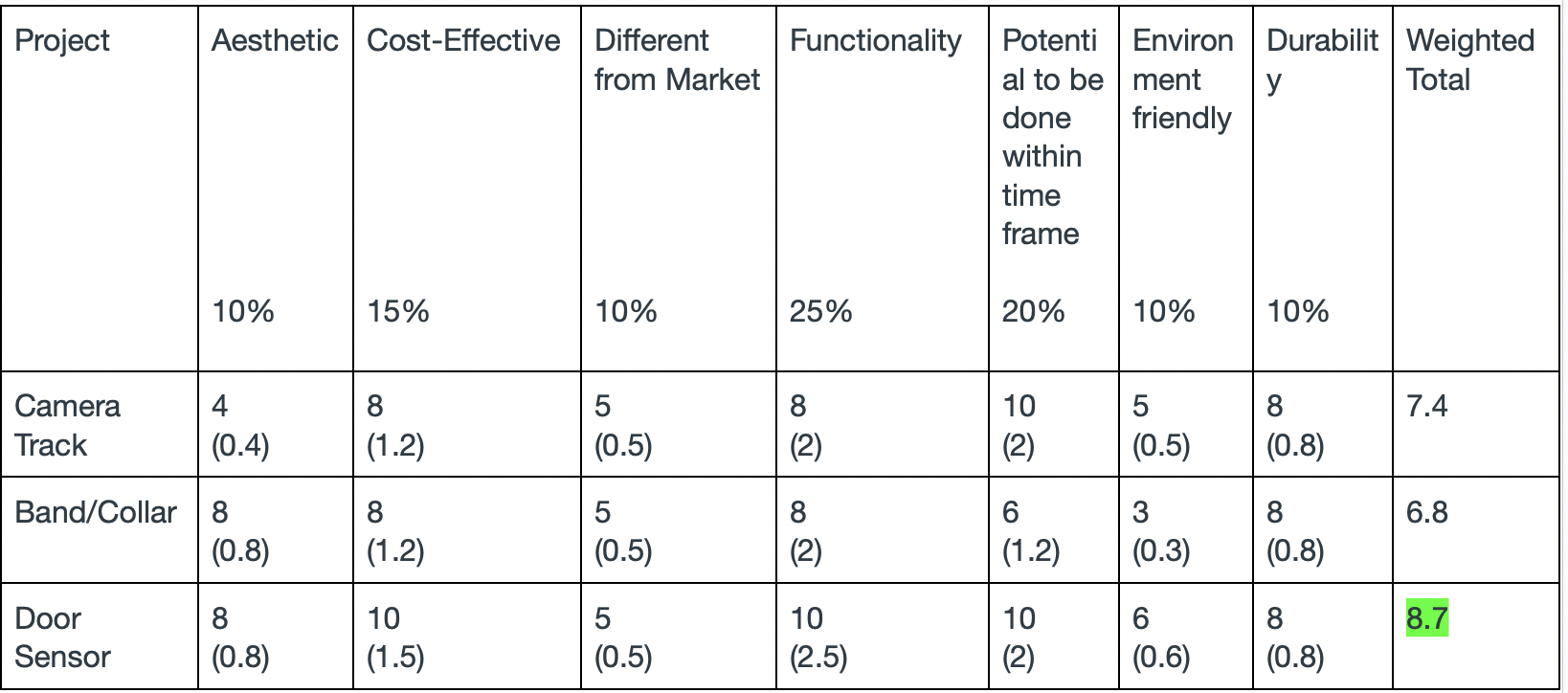
Weighted rating matrix — reed switch design scored highest overall.
5.0 Configuration Design
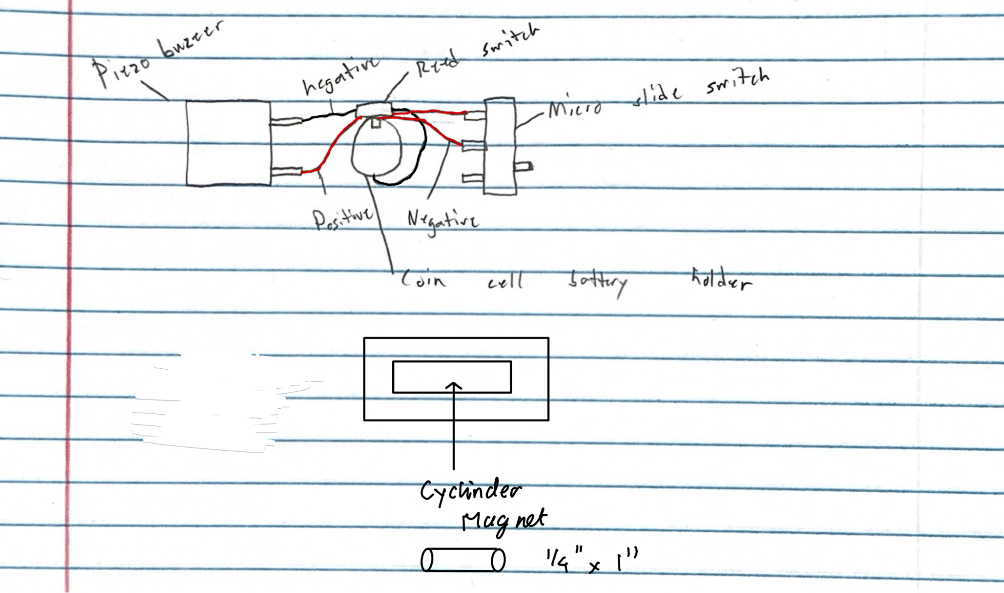
5.1 Layout Sketch
The door sensor consists of two housings:
Transmitter Housing: Attached to the door frame, containing the reed switch, battery, piezo buzzer, and wiring.
Magnet Housing: A small enclosure mounted on the door, aligned with the reed switch to maintain a closed circuit while the door is shut.
When the door opens, the magnet moves away from the reed switch, causing it to close the circuit and activate the buzzer. The device operates independently without requiring Wi-Fi or an external power source.
5.2 Functional Decomposition
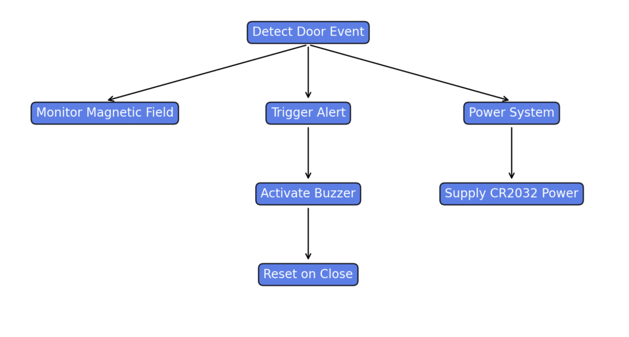
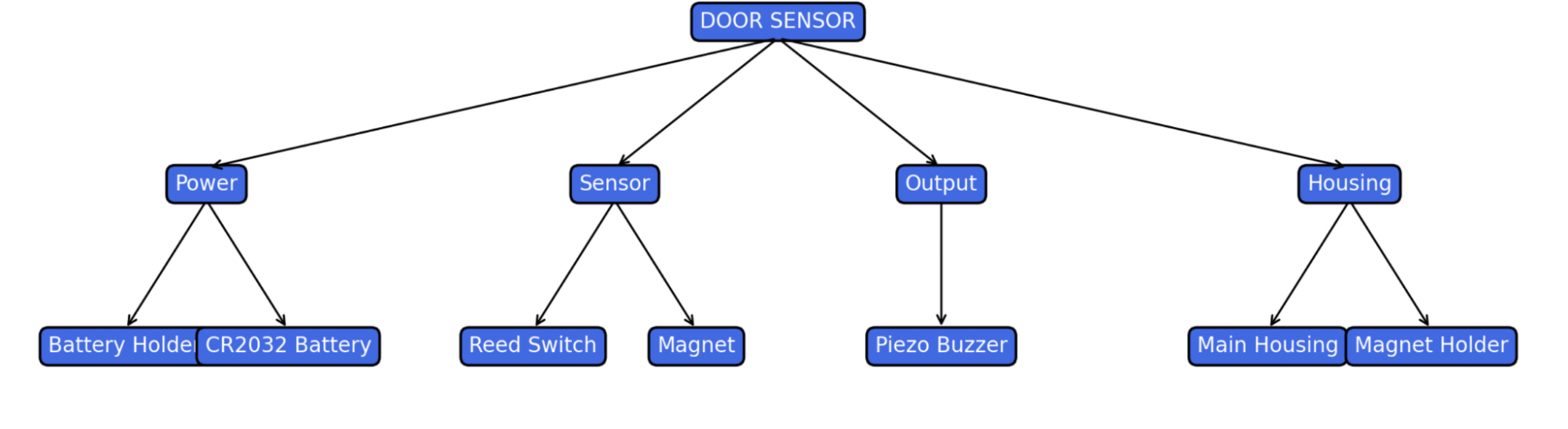
5.3 Component Decomposition
6.0 Parametric Design
6.1 Design for Assembly (DFA)
To ensure simplicity and reliability, the door sensor was designed using as few components as necessary. The assembly process was optimized for minimal tools, ease of alignment, and safe handling.
Design for Assembly Checklist:
- ✅ Minimal part count (magnet, reed switch, buzzer, battery, and housing)
- ✅ No soldering required if using jumper clips or pre-soldered components
- ✅ Snap-fit or screw-in housing for easy access
- ✅ Standard, low-cost components
- ✅ Compact modular design (sensor unit and magnet housing)
- ✅ Assembly instructions included
- ✅ Minimal tools required (small screwdriver or adhesive tape)
Key Features:
- The housing is made of two 3D-printed or plastic parts that align with door and frame edges.
- The reed switch and buzzer are pre-positioned and require minimal wiring.
- A coin cell battery snaps into a holder, eliminating the need for power cables.
The door sensor is engineered to be energy-efficient, responsive, and durable for indoor residential use.
Design for Function Checklist:
- ✅ Strong plastic housing for durability
- ✅ Low power consumption for long battery life (~6 months on CR2032)
- ✅ Reed switch for fast, passive sensing
- ✅ Loud mini piezo buzzer (~85 dB) for clear alerts
- ✅ Safe, low-voltage operation (3V)
- ✅ Compact size for discreet installation
- ✅ Simple wiring minimizes failure points
- ✅ Reliable magnetic alignment system
- ✅ Easy access for battery replacement
Functional Performance Goals: Functional Performance Goals:
- Must alert immediately upon door opening
- Must reset automatically once door is closed
- Must operate reliably for over 1,000 cycles
- Must require no maintenance other than battery replacement
6.2 CAD & Assembly Drawing
Door Sensor Housing
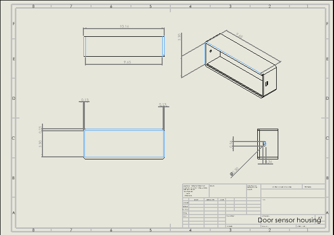
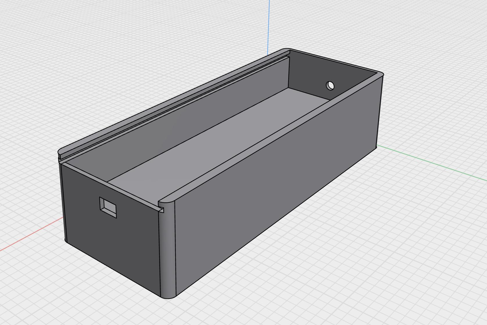
- There are two cutouts in the housing design. The rectangular hole is for the on/off switch, allowing users to easily enable or disable the alarm system. The circular hole is positioned to align with the mini piezo buzzer, allowing the sound to pass clearly through the enclosure for effective audio alerts.
- Additionally, there is a slot at the top designed for a sliding lid. This feature allows users to open the housing conveniently to replace the battery, perform maintenance, or upgrade components. It also supports easier disassembly for recycling at the end of the device’s life cycle.
- Inside the main housing, we securely place the reed switch, battery holder, and power switch, then solder the connections to complete the circuit.
Sliding Cover
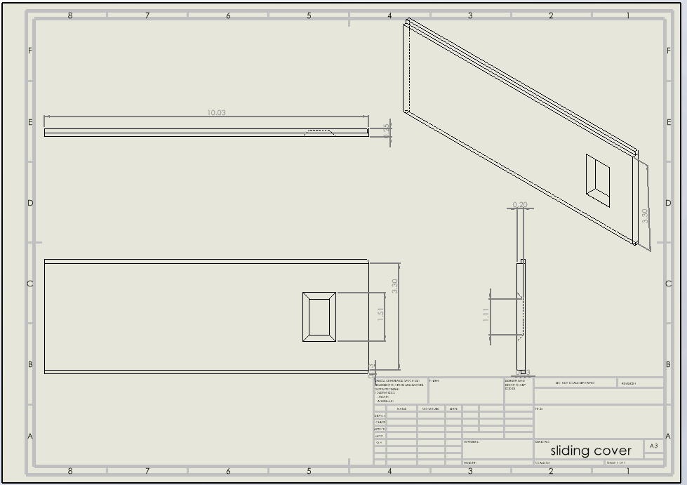
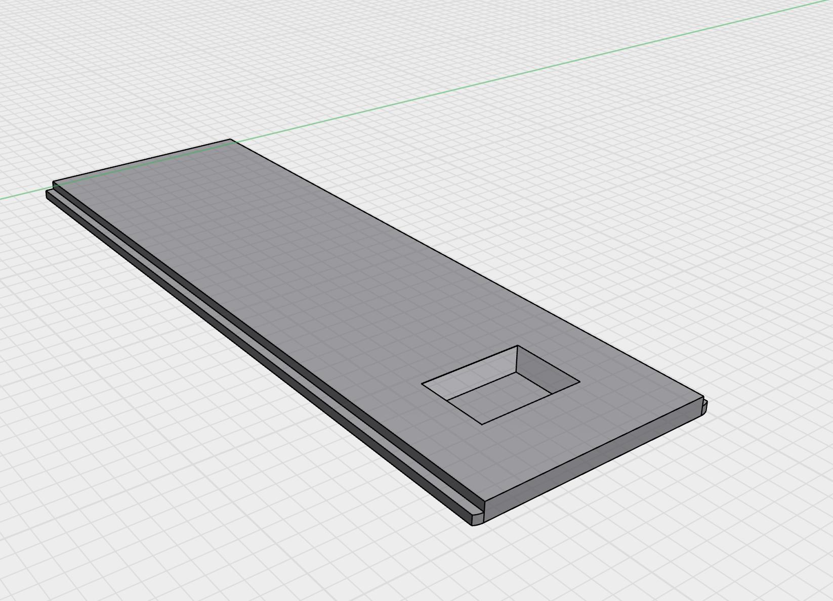
- This is the sliding lid for the main housing. We designed a chambered cutout to provide users with a convenient grip area, making it easy to slide the lid open or closed. Additionally, the rails were precisely cut and fitted to ensure the lid aligns securely with the housing, forming a tight seal that helps prevent water and dirt from entering and damaging the internal components.
Magnet Housing
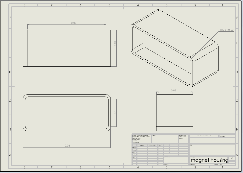
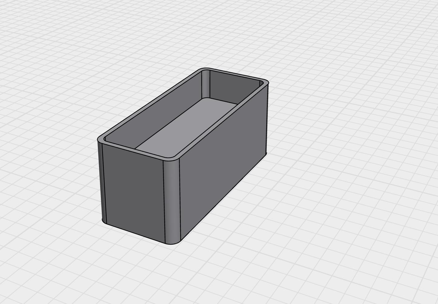
- This is the magnet holder, designed to be mounted on the door frame, positioned close to the main housing. The main housing, which contains the electronics, is mounted on the moving part of the door. When the door is closed, the magnet aligns with the reed switch in the main housing to maintain the circuit's inactive state. Opening the door causes the magnet to move away, triggering the alarm.
Magnet Cover
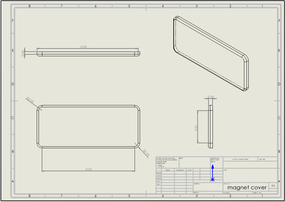
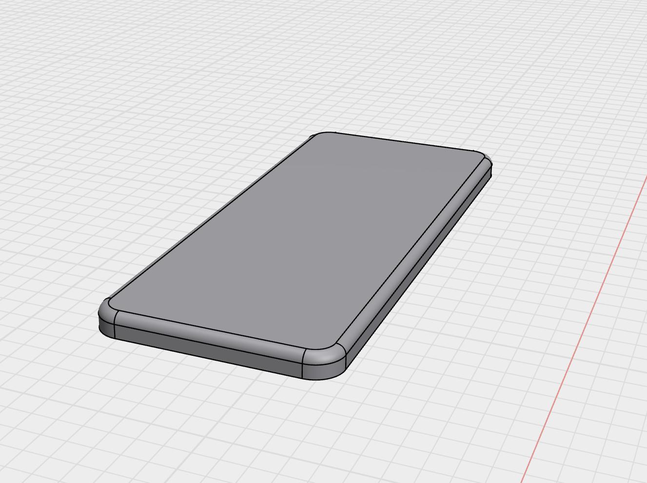
- The magnet cover serves to protect the magnet from physical damage and environmental exposure while also providing a clean, aesthetically pleasing appearance.
7.0 Engineering Analysis
7.1 Power Consumption and Battery Life
The door sensor is powered by a CR2032 coin cell battery (3V, ~220 mAh). The circuit consists of a reed switch (passive), a mini piezo buzzer, and minimal wiring. Most of the time, the device draws virtually no current due to the open reed switch. Current only flows when the door is opened and the circuit is triggered.
Assumptions:
- Reed switch: passive (0 mA)
- Piezo buzzer: draws ~15 mA when active
- Buzz duration: ~2 seconds per activation
- Door opens ~20 times per day

Power consumption calculation — average daily current draw estimated.
Add estimated idle leakage current: ~0.05 mA Total average current draw ≈ 0.057 mA Estimated Battery Life: ~5 to 6 months
7.2 Response Time
The reed switch closes almost instantaneously (~1 ms) when the magnet moves away. The piezo buzzer activates immediately upon switch closure. This ensures the alert is triggered as soon as the door opens, providing near real-time feedback.
Conclusion:
- Switch Response Time: <1 ms
- Audible Alert Delay: <10 ms
- System responsiveness is excellent for the intended use
7.3 Sound Output
The mini piezo buzzer emits sound in the range of 80–90 dB, sufficient to alert someone in a small room or hallway. This level was chosen to be noticeable but not irritating.
7.4 Range & Alignment
The magnetic reed switch activates when the magnet is within approximately 10 mm. Careful alignment of the sensor housing and magnet enclosure ensures consistent triggering.
Key Notes:
- Misalignment beyond 10 mm may prevent activation
- Neodymium magnets are preferred for stronger fields
8.0 Testing
8.1 Test 1 – Circuit Functionality
Objective:
Verify that the reed switch properly triggers the piezo buzzer when the magnetic field is disrupted.
Clarification:
The reed switch used in our circuit has three wires: one input wire, and two output wires (a short leg and a long leg).
- The short leg corresponds to a normally closed (NC) contact.
- The long leg corresponds to a normally open (NO) contact.
Since we want the mini piezo buzzer to activate when no magnet is detected (i.e., when the door is open), we connect the long leg (NO contact) to the piezo buzzer. This ensures that when the magnet is present, the circuit is open and the buzzer is off. When the magnet moves away, the circuit closes through the NO contact, allowing current to flow and the buzzer to sound.
Procedure:
- Connected the reed switch, piezo buzzer, and CR2032 battery on a breadboard
- Aligned a neodymium magnet with the reed switch
- Moved the magnet away to simulate a door opening
Result:
The buzzer activated immediately upon moving the magnet, confirming that the reed switch triggered correctly. The circuit returned to idle when the magnet was brought back. The response time was under 10 ms.
8.2 Test 2 – Magnetic Range
Objective:
Determine the maximum distance at which the reed switch responds to the magnet.
Procedure:
- Incrementally increased the distance between the magnet and the reed switch
- Recorded the maximum gap at which the circuit still activated the buzzer
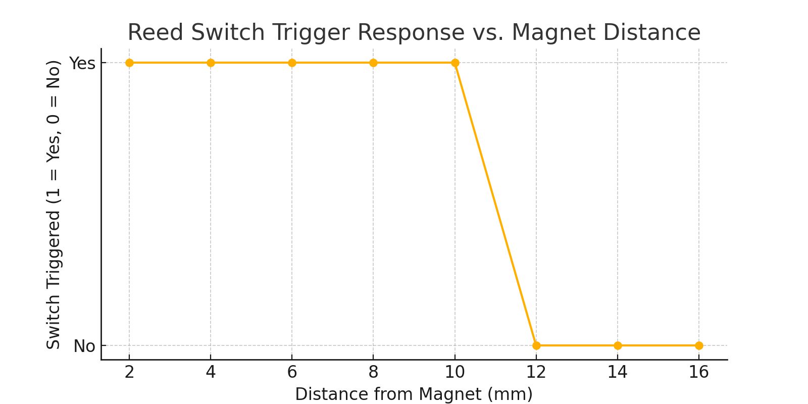
Reed switch trigger response vs. magnet distance — the switch activates reliably up to ~10 mm.
Result:
The reed switch consistently activated the buzzer when the magnet was within approximately 10 mm. Beyond this distance, the circuit failed to trigger reliably.
8.3 Test 3 – Sound Audibility
Objective:
Evaluate the loudness of the buzzer in a typical indoor environment.
Procedure:
- Activated the buzzer in a quiet room
- Used a sound level meter to measure the decibel output at 1 meter
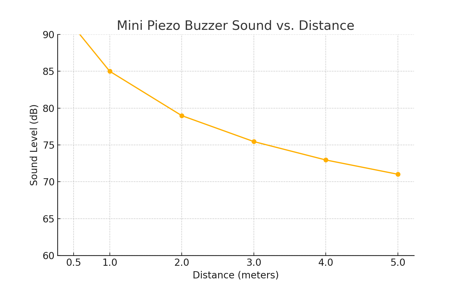
Mini piezo buzzer sound vs. distance — sound level.
Result:
The buzzer produced a sound level of approximately 85 dB at 1 meter, which is comparable to the loudness of city traffic and sufficient to alert users in a household environment.
8.4 Test 4 – Battery Life
Objective:
Estimate battery longevity under realistic usage conditions.
Assumptions:
- 20 door openings per day
- 2-second buzzer activation per event
- 0.057 mA average current draw (as calculated in Section 7)
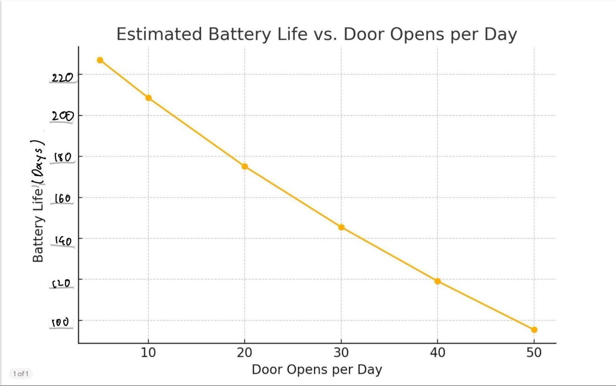
Estimated battery life vs. door opens per day — battery longevity.
Result:
Based on the assumptions, the CR2032 coin cell battery is expected to last approximately 180 days (6 months) under typical use. Increased door activity shortens battery life, while fewer daily activations extend it.
8.5 Conclusion and Recommendations
Conclusion
Through iterative prototyping and testing, our team successfully developed a compact, low-cost, and energy-efficient door sensor. The device performs reliably using a magnetic reed switch and piezo buzzer to alert users when a door is opened. Key test results demonstrated:
- Immediate response (<10 ms) upon magnetic disruption
- Audible buzzer output around 85 dB, effective for indoor alerts
- Reliable activation within a 10 mm magnet range
- Projected battery life of approximately 5–6 months using a CR2032 coin cell
The overall system met its core performance goals and user-centered design criteria, including ease of use, modular construction, and minimal maintenance.
Recommendations
For future improvement and scaling, we recommend:
- Adding Wireless Capabilities – Integrating a low-power wireless module (e.g., BLE or LoRa) could enable remote notifications to smartphones or smart home hubs.
- Weatherproofing the Housing – Sealing the housing with gaskets or silicone would allow for outdoor or semi-outdoor use.
- PCB Integration – Replacing hand-wiring with a printed circuit board (PCB) would improve durability, consistency, and ease of assembly.
- User Interface Enhancement – Incorporating an LED indicator or adjustable buzzer tone could improve user interaction and accessibility.
- Modular Battery Design – Designing for AA or rechargeable battery packs could provide longer life or environmental benefits.
FINAL TEST DATA
Reed switch trigger response vs. magnet distance — the switch activates reliably up to ~10 mm.
Mini piezo buzzer sound vs. distance — sound level.
Estimated battery life vs. door opens per day — battery longevity.
Appendix
A. Gantt Chart Schedule
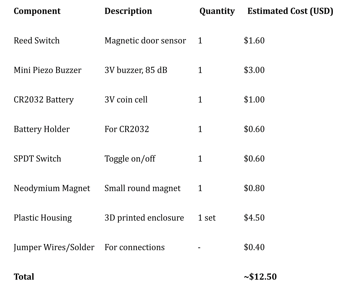
B. Bill of Materials (BOM)
C. Operation
Instructions for Use
1. Mount the Sensor:
- Attach the main housing (with reed switch and buzzer) to the door using adhesive or screws.
- Align and mount the magnet housing on the door frame, directly across from the reed switch.
2. Insert Battery:
- Slide open the top lid.
- Insert a CR2032 coin cell battery into the holder with correct polarity.
- Close the lid securely.
3. Activate the Alarm:
- Use the power switch to turn the sensor on.
- When the door opens (magnet moves away), the buzzer will sound.
4. Turn Off the Alarm:
- Slide the switch to the off position to disable the buzzer.
Demo
Demonstration video of the door sensor in operation.